TC-5915AU RF Shield Box

Provides RF shield and signal connections necessary for testing mobile wireless devices, such as mobile cell phones or WLAN devices. The TC-5915AU RF Shield box has two RF ports and two EMI filtered data ports. With the RF coupling accessory and filtered control ports, the TC-5915AU RF Shield Box makes an ideal solution for RF testing mobiles and small RF devices on test benches for R&D, Service, and QA. This RF Shield box is ideal when you need the flexibility of a little extra room for the device being tested.

Request Quote Download Data Sheet

SKU: TC-5915AU Categories: ,

Description

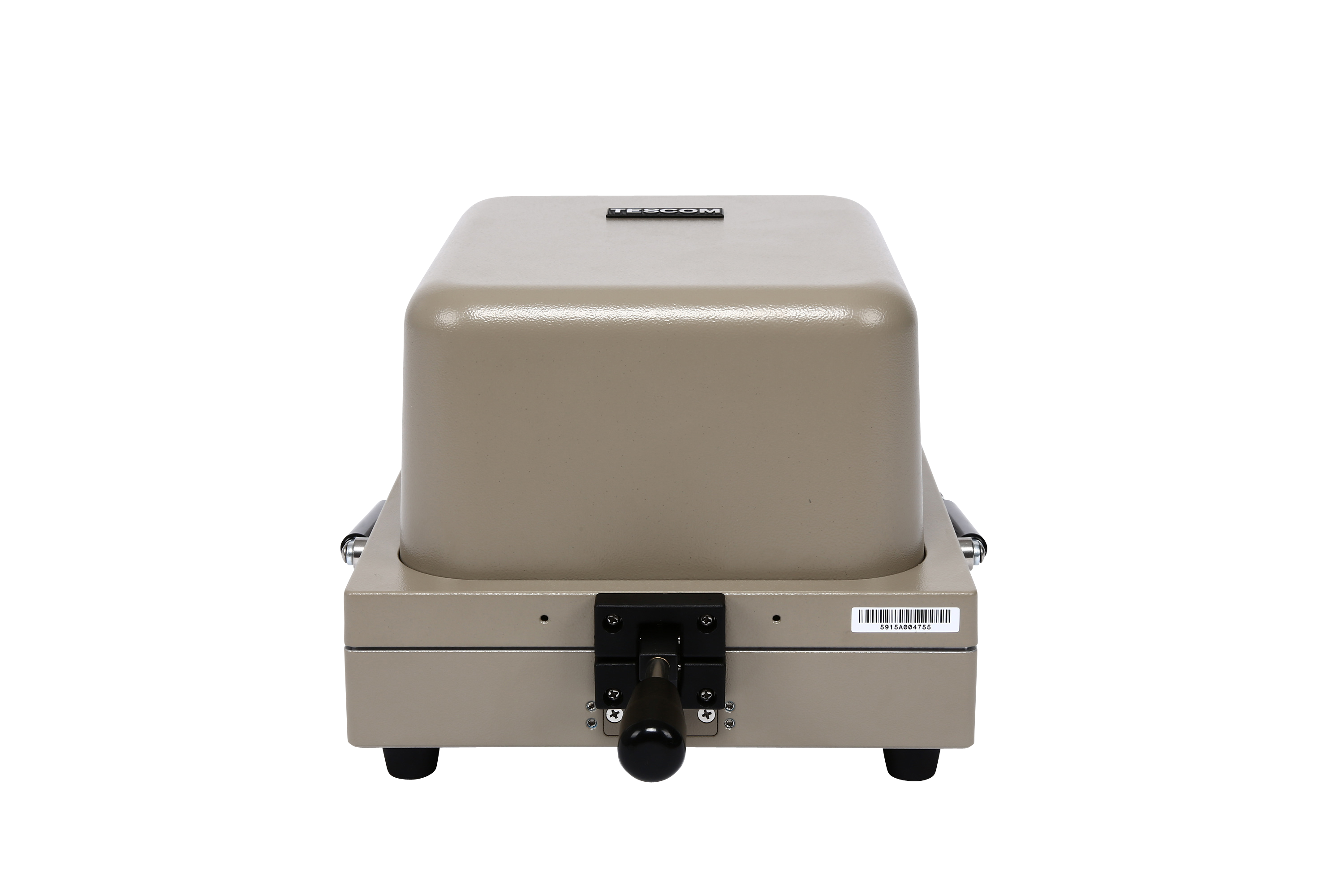
TC-5915AU RF Shield Box Key Features

  • Upgraded “U” version of the TC-5915A increases isolation performance to 12GHz
  • High RF Shielding up to 12 GHz
  • Manual Operation, Ergonomic
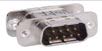
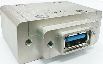
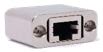
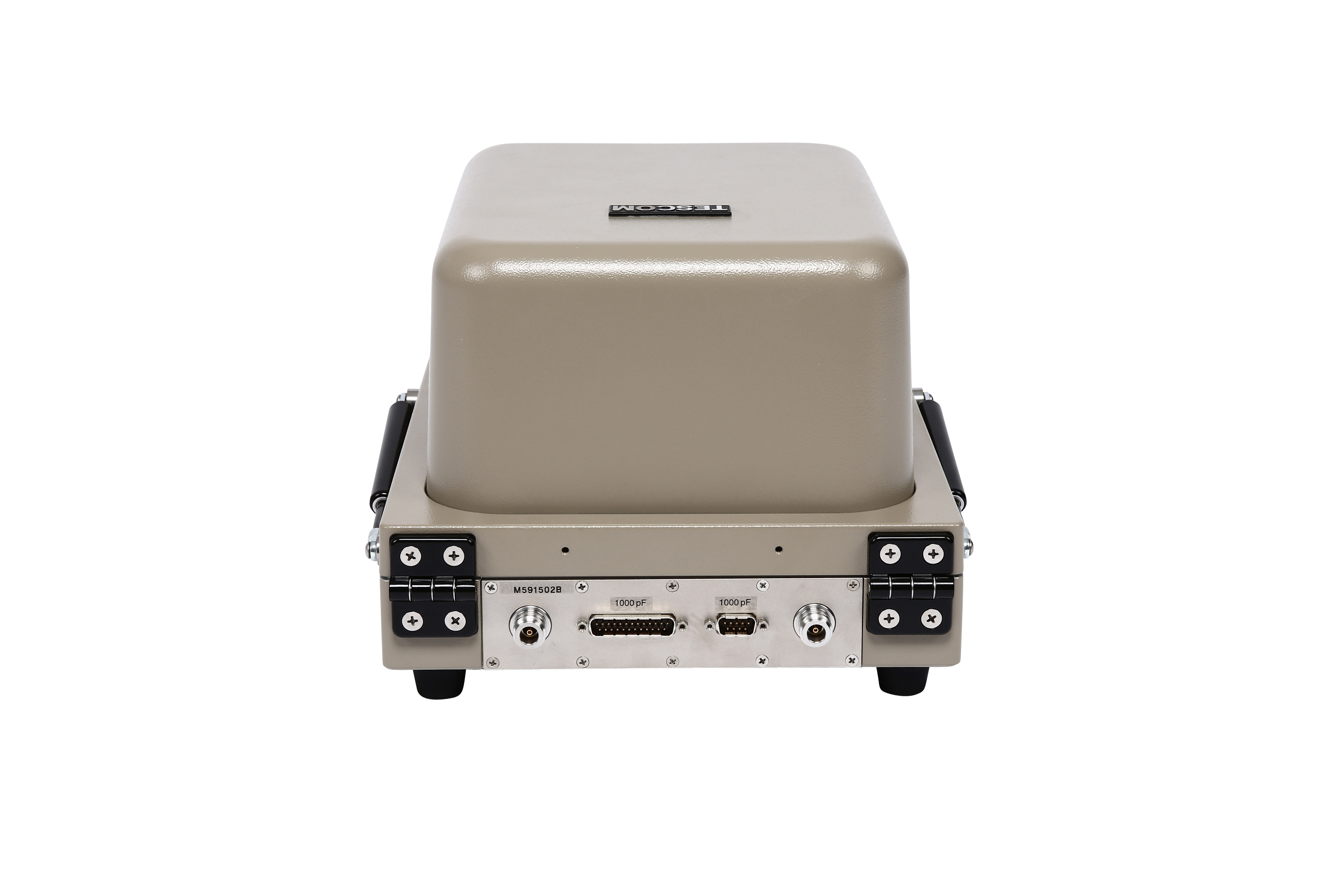
  • Easily Customizable IO Plate to meet RF testing needs
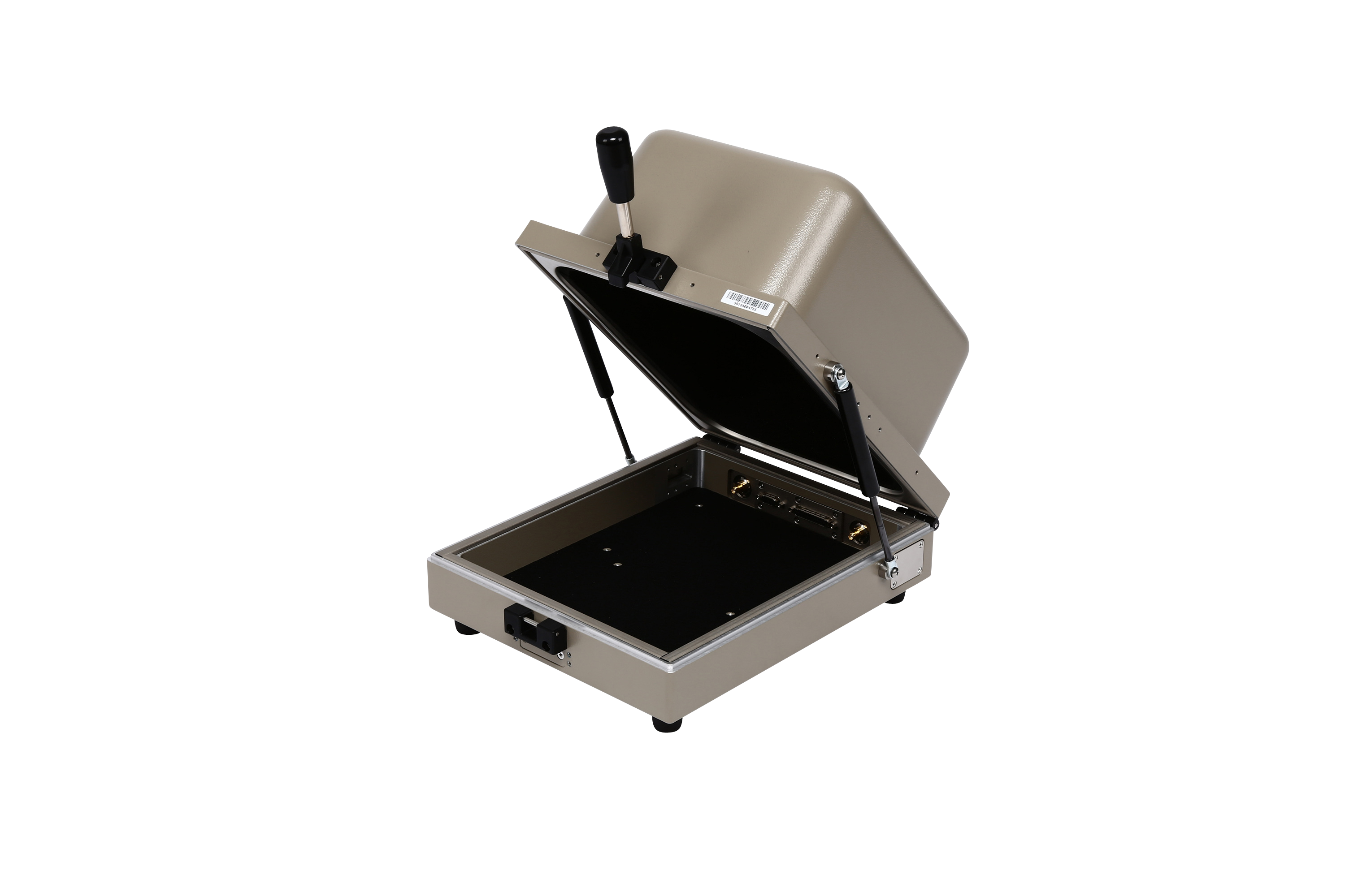
  • Shock Absorbers on lid

The New TESCOM TC5915AU RF Shield Box is the upgraded version of the popular TC5915AU. The new DU version now provides excellent reliable RF Shielding up to 12GHz.  It still retains the basic features of the TC5915AU RF Shield Box that the testing industry has grown to love but now with improved shielding to meet the higher frequency testing demands of wireless technology.  This Faraday cage is designed for OTA testing as all the interior walls are lined with highly absorbent RF Absorber along with a layer of ferrite absorber to minimize reflections for performing Over-the-Air testing(OTA).  Add one of our grid fixtures and antenna couplers to make the TC5915AU RF Shield Box an ideal OTA test solution for your handheld DUT(Device-Under-Test).

How is Over-The-Air, OTA testing performed? In order to perform an OTA test, the device under test (DUT) must be placed in a test chamber, such as the TC5915AU RF Shield Box to isolate the device from outside interference.

Many factors can affect the performance and reliability of the OTA testing, such as reflections causing multipath conditions and interference from the surrounding environment, so RF absorber is added to the interior walls to help mitigate reflections and the shield box to isolate the device under test.

SPECIFICATIONS SUBJECT TO CHANGE WITHOUT PRIOR NOTICE

Additional information

Weight 6 kg
Dimensions 11 × 8.6 × 6.2 in
Function

Manual

Internal Depth

10-15in

Internal Height

6-10in

Internal Width

8-12in

Manufacturer

Tescom

Specifications

TC-5915AU Manual RF Shield Box Mechanical Specifications

  • RF Shield Box Effectiveness: >70dB, DC ~ 2.5GHz
  • RF Connectors: 2 N-Type(f) Outside and SMA(f) Inside
  • Data Connectors: DB25 and DB9, RF filtered, 100 VDC, 3A Max
  • Inner Dimension: 9.3(W) x 11.7(D) x 6.7(H) inches
  • Outer Dimension: 12.2(W) x 18.6(D) x 8.7(H) inches
  • Weight without accessories: 13.2 lbs
  • Supplied Accessories: 1 Type-N RF Cable, 1 DB9 and 1 DB25 Data Cables
SPECIFICATIONS SUBJECT TO CHANGE WITHOUT PRIOR NOTICE

Typical RF Shielding

TC-5915AU Manual RF Shield Box Typical RF Shielding

The shield effectiveness below is measured when the blank panel is mounted; other I/O interface panel results a different shielding effectiveness of the shield box.

  • 100 to 3000 MHz > 70 dB
  • 3  to 6 GHz > 60 dB
  • 6 to 12 GHz > 60 dB

***Isolation example above is based on I/O configuration as specified above. Isolation may be higher or lower based on specific I/O configuration installed.

Custom Configurations

TC Manual RF Shield Box Custom I/O Interface Panel

Customized I/O Interface panels are available. Please contact the CTS sales team for more information

*SPECIFICATIONS SUBJECT TO CHANGE WITHOUT PRIOR NOTICE

  • Each shielding effectiveness is measured when each I/O interface panel, which is shown above, is mounted.
  • Above data was measured by Tescom, The Shielding Effectiveness might be different based on the measuring method and condition.
  • This data has been measured under the condition that the cables are not connected to each filters. When the cables are connected it can affect the shielding performance.