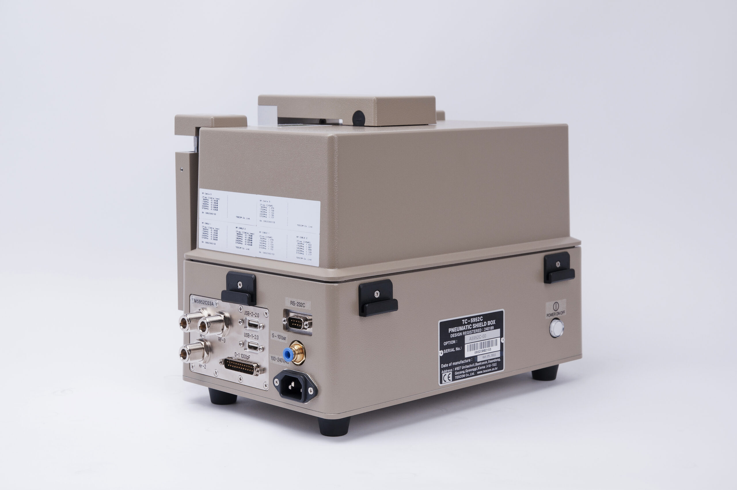
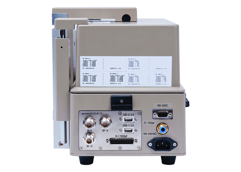
Description
TC-5952C Pneumatic RF Shield Box Key Benefits
- High RF Shieling
- Pneumatic control of lid open-close and optional test fixture motions
- EMI filters on all data and DC lines
- Easily customizable to meet various testing needs
- RS-232C Remote Control
- Red and Green LED’s for Pass/Fail indication
- Dual pressure control and Lid Down Sensor for safety
- Narrower side front
- Provide shield protective cover for safety.
- The custom fixture option, F5942A/B allows auto connection, so it is efficient for mass production.
- CS compliant: EN 292-1:1991, EN 292-2:1991/A1:1995, EN 983:1996, EN 1050:1996, EN 60204-1:1997
SPECIFICATIONS SUBJECT TO CHANGE WITHOUT PRIOR NOTICE
Typical RF Shielding
Typical RF Shielding
The shield effectiveness below is measured when the blank panel is mounted; other I/O interface panel results a different shielding effectiveness of the shield box.
- 100 to 2000 MHz > 70 dB
- 2000 to 3000 MHz > 70 dB
- 3000 to 6000 MHz > 60 dB
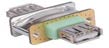
Custom Configurations
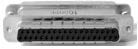
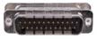
TC Manual RF Shield Box Custom I/O Interface Panel
Customized I/O Interface panels are available. Please contact the CTS sales team for more information
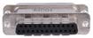
| I/O Interface | Order Number | Typical Data Rate/Line Voltage | Typical Shielding* |
DB37, 1000pF pi Filter | 3409-0012-1 | 3 Mbps / 100 VDC,
5 Amps max | >70 dB from 0.5 to 2 GHz
>80 dB from 2 to 3 GHz
>70 dB from 3 to 6 GHz |
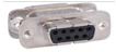
DB25, 1000pF pi Filter | 3409-0009-1 | 3 Mbps / 100 VDC,
5 Amps max | >70 dB from 0.5 to 2 GHz
>80 dB from 2 to 3 GHz
>70 dB from 3 to 6 GHz |
DB25, 100pF pi Filter | 3409-0014-1 | 10 Mbps / 100 VDC,
5 Amps max | >50 dB from 0.5 to 2 GHz
>60 dB from 2 to 3 GHz
>60 dB from 3 to 6 GHz |
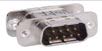
DB9, 1000pF pi Filter | 3409-0008-1 | 3 Mbps / 100 VDC,
5 Amps max | >70 dB from 0.5 to 2 GHz
>80 dB from 2 to 3 GHz
>70 dB from 3 to 6 GHz |
DB9, 100pF pi Filter | 3409-0010-1 | 10 Mbps / 100 VDC,
5 Amps max | >50 dB from 0.5 to 2 GHz
>60 dB from 2 to 3 GHz
>60 dB from 3 to 6 GHz |
USB 2.0 Filter | 3409-0018A-3 | 480 Mbps / 5 V, 500 mA /
Max Current: 5A | >60 dB from 0.5 to 2 GHz
>70 dB from 2 to 3 GHz
>70 dB from 3 to 6 GHz |
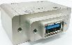
USB 3.0 Filter(Active) | 3409-0042A-1 | 5000 Mbps / 5 V, 900 mA /
Max Current: 1.5 A | >70 dB from 0.5 to 2 GHz
>70 dB from 2 to 3 GHz
>55 dB from 3 to 6 GHz |
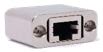
RJ-45 Filter | 3409-0022A | 1 Gbit/s Copper-Line
Ethernet (1000 BASE-T) | >60 dB from 0.5 to 2 GHz
>70 dB from 2 to 3 GHz
>70 dB from 3 to 6 GHz |
DC Power Adaptor | 3406-0004A | 50 VDC,
3 Amps max | >70 dB from 0.5 to 2 GHz
>80 dB from 2 to 3 GHz
>80 dB from 3 to 6 GHz |
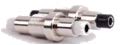
DC Power Adaptor,
Banana Jack Type | 3406-0005A
3406-0006A | 50 VDC,
10 Amps max | >70 dB from 0.5 to 2 GHz
>80 dB from 2 to 3 GHz
>80 dB from 3 to 6 GHz |

AC Power Adaptor | 3103-0009A | 250 VAC,
7 Amps max | >70 dB from 0.5 to 2 GHz
>80 dB from 2 to 3 GHz
>80 dB from 3 to 6 GHz |
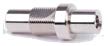
RF, N-SMA Connector | 3408-0038 | | >60 dB from 0.5 to 2 GHz
>70 dB from 2 to 3 GHz
>70 dB from 3 to 6 GHz |

RF, SMA-SMA Connector | 3408-0039 | | >60 dB from 0.5 to 2 GHz
>70 dB from 2 to 3 GHz
>70 dB from 3 to 6 GHz |
*SPECIFICATIONS SUBJECT TO CHANGE WITHOUT PRIOR NOTICE
- Each shielding effectiveness is measured when each I/O interface panel, which is shown above, is mounted.
- Above data was measured by Tescom, The Shielding Effectiveness might be different based on the measuring method and condition.
- This data has been measured under the condition that the cables are not connected to each filters. When the cables are connected it can affect the shielding performance.